Shock Absorber Replacement
Removal Procedure
Notice: The front shock absorbers of the vehicle are multifunctional. In addition to contributing to a smooth ride they also provide the only stop to the front suspension when fully extended. Therefore, when servicing the shock absorber, service replacement shock absorbers must be equivalent to original shock absorbers in both extended length and strength. Use of shocks not complying to original equipment or strength could result in suspension over-travel or shock breakage. Suspension over-travel may result in suspension component breakage.
1. Raise and support the vehicle. Refer to Vehicle Lifting.
2. Disconnect the electrical connector using the following procedure if equipped with selectable ride.
3. Disconnect the Real Time Damping (RTD) link rod from the sensor (if equipped). Refer to Front Position Sensor Link Assembly Replacement - Electronic Suspension.
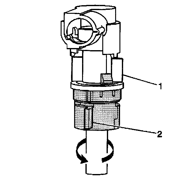
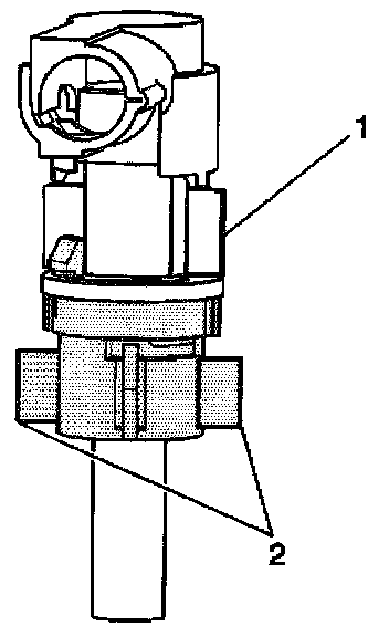
4. Grasp the connector lock tabs (1,2). Rotate the connector tabs counterclockwise until the connector is unlocked.
5. Disengage the connector from the tennon by firmly pulling the connector up.
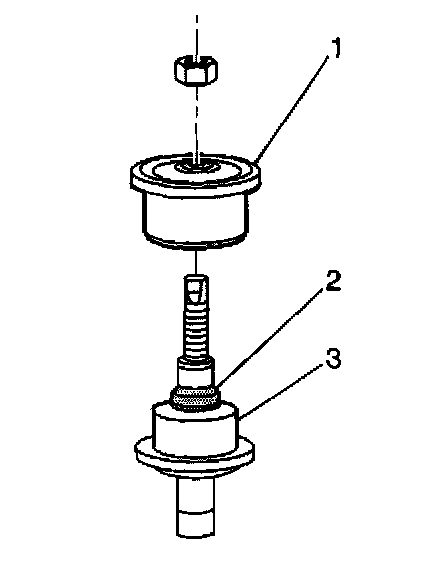
6. Hold the tennon end with a wrench while removing the nut.
7. Remove the nut.
8. Remove the upper insulator (1). Do not discard the plastic pilot ring (2).
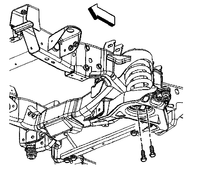
9. Remove the shock absorber mounting bolts at the lower control arm.
10. Remove the shock absorber through the lower control arm from below.
Installation Procedure
1. Support the lower control arm with a suitable jack in order to align the tennon with the mounting hole if equipped with selectable ride.
2. Install the shock absorber through the lower control arm from below. Insert the tennon through the mounting hole in the upper spring pocket.
3. Align the shock absorber with the mounting holes in the lower control arm.
Notice: Refer to Fastener Notice in Service Precautions.
4. Install the shock absorber mounting bolts to the lower control arm.
- Tighten the bolts to 25 Nm (18 ft. lbs.).
Important: The upper insulators are substantially larger that the lower insulators. The upper insulator (1) must be installed above the shock mounting bracket on the frame. The plastic pilot ring (2) will assist the alignment of the isolators.
5. Install the upper insulator to the shock absorber.
6. Install the nut to the tennon end. Do not tighten the nut.
7. Connect the RTD link rod to the sensor (if equipped). Refer to Front Position Sensor Link Assembly Replacement - Electronic Suspension.
8. Remove the safety stands.
9. Lower the vehicle.
10. Hold the tennon end with a wrench while torquing the nut.
- Tighten the nut to 20 Nm (15 ft. lbs.).
11. Connect the electrical connector using the following procedure if equipped with selectable ride.
11.1. Verify that the connector is unlocked.
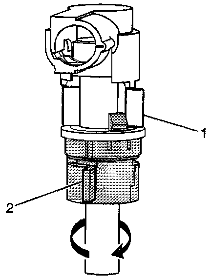
11.2. Align the connector so that the tabs (1 ) are perpendicular to the wrench flats on the tennon end.
11.3. Engage the connector to the tennon by firmly pushing the connector down.
11.4. Grasp the connector lock tabs (1, 2). Rotate the connector counterclockwise.
12. The connector is locked into place when you hear an audible snap and the tabs (1, 2) are aligned.
13. Dispose of the shock absorber. Refer to Shock Absorber Disposal.