Front Steering Knuckle: Service and Repair
STEERING KNUCKLE REPLACEMENT
- Tools Required
- J 43631 Ball Joint Separating Tool
Removal Procedure
1. Raise and support the vehicle. Refer to Vehicle Lifting.
2. Remove the tire and wheel. Refer to Tire and Wheel Removal and Installation.
3. Remove the wheel hub and bearing. Refer to Wheel Hub, Bearing, and Seal Replacement.
4. Disconnect the Real Time Damping (RTD) link rod from the sensor (if equipped). Refer to Front Position Sensor Link Assembly Replacement - Electronic Suspension in Real Time Damping.
5. Support the lower control arm with a suitable jack.
6. Disconnect the outer tie rod from the knuckle. Refer to Tie Rod End Replacement - Outers or Tie Rod Replacement in Steering Linkage (Non- Rack and Pinion).
7. Remove the brake hose bracket retaining bolt from the knuckle.
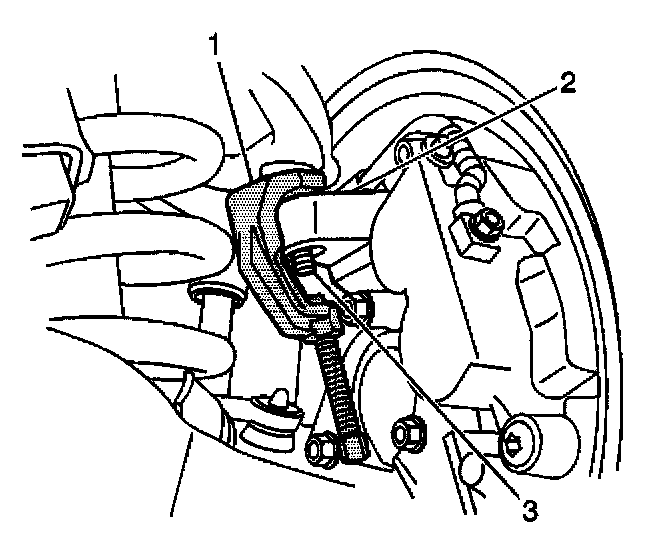
8. Remove the retaining nut and separate the upper ball joint from the steering knuckle (2) using the J43631 (1)
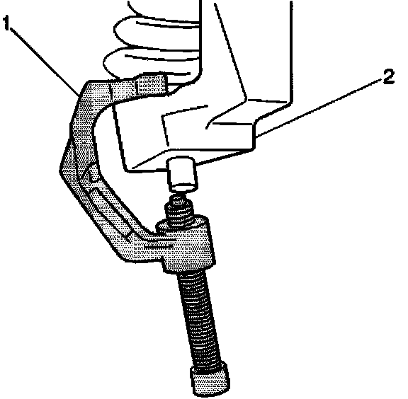
9. Remove the retaining nut and separate the lower ball joint from the steering knuckle (2) using the J43631 (1)
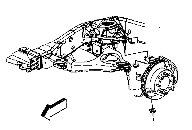
10. Remove the steering knuckle.
Installation Procedure
1. Clean all grease and contaminants from the tapered section and the threads of the upper ball joint, the lower ball joint, and the tie rod end.
2. Clean and inspect the taper holes and the mounting surfaces of the steering knuckle. If any of the tapered holes are elongated, out of round, or damaged, the replace the steering knuckle.
3. Install the steering knuckle.
Notice: Refer to Fastener Notice in Service Precautions.
4. Connect the lower ball joint to the steering knuckle and install the retaining nut.
- Tighten the retaining nut to 100 Nm (74 ft. lbs.).
5. Connect the upper ball joint to the steering knuckle and install the retaining nut.
- Tighten the retaining nut to 50 Nm (37 ft. lbs.).
6. Install the brake hose bracket retaining bolt to the knuckle.
- Tighten the bolt to 9 Nm (80 inch lbs.).
7. Connect the outer tie rod to the steering knuckle. Refer to Tie Rod End Replacement - Outers or Tie Rod Replacement.
8. Install the wheel hub and bearing. Refer to Wheel Hub, Bearing, and Seal Replacement.
9. Connect the RTD link rod to the sensor (if equipped). Refer to Front Position Sensor Link Assembly Replacement - Electronic Suspension in Real Time Damping.
10. Install the tire and wheel. Refer to Tire and Wheel Removal and Installation.
11. Remove the safety stands.
12. Lower the vehicle.