Front Upper
- Tools Required
- J 43631 Ball Joint Separator
Removal Procedure
1. Raise and support the vehicle. Refer to Vehicle Lifting.
2. Remove the tire and wheel. Refer to Tire and Wheel Removal and Installation.
3. Disconnect the Real Time Damping (RTD) link rod from the sensor (if equipped). Refer to Front Position Sensor Link Assembly Replacement - Electronic Suspension in Real Time Damping.
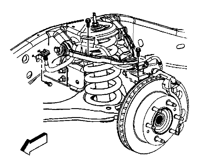
4. Remove the retaining bolt for the brake hose and the wheel speed sensor brackets.
5. Remove the wheel drive shaft. Refer to Wheel Drive Shaft Replacement.
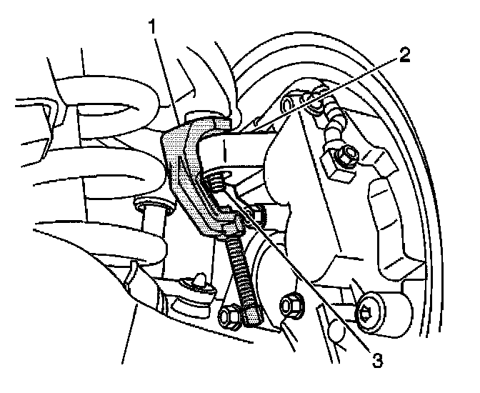
6. Remove the nut at the upper ball joint. Discard the nut.
7. Disconnect the upper control arm from the steering knuckle using the J 43631(1).
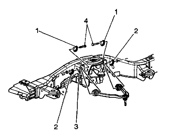
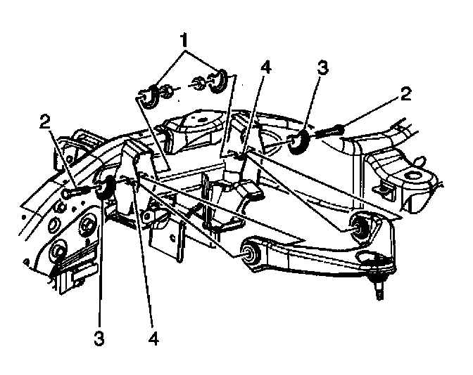
8. Remove the upper control arm nuts and the adjustment cams (2) (15 Series RWD, 4WD, and 25 Series RWD).
9. Remove the upper control arm bolts (4) (15 Series RWD, 4WD, and 25 Series RWD).
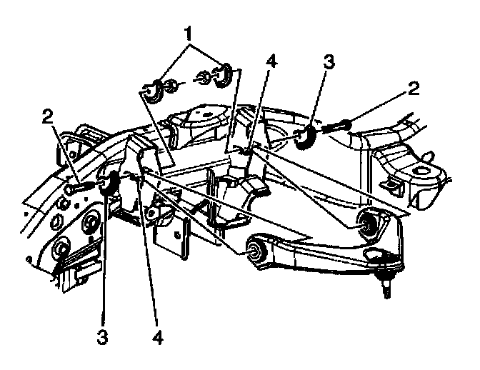
10. Remove the upper control arm nuts and the adjustment cams (2) (25 Series 4WD).
11. Remove the upper control arm bolts (4) (25 Series 4WD).
12. Remove the upper control arm.
Installation Procedure
1. Install the upper control arm.
2. Install the upper control arm bolts (4) (25 Series 4WD).
Notice: Refer to Fastener Notice in Service Precautions.
3. Install the upper control arm nuts and the adjustment cams (2) (25 Series 4WD).
- Tighten the nuts to 190 Nm (140 ft. lbs.).
4. Install the upper control arm bolts (4) (15 Series RWD, 4WD, and 25 Series RWD).
5. Install the upper control arm nuts and the adjustment cams (2) (15 Series RWD, 4WD, and 25 Series RWD).
- Tighten the nuts to 190 Nm (140 ft. lbs.).
6. Connect the upper control arm to the steering knuckle.
7. Install the wheel drive shaft. Refer to Wheel Drive Shaft Replacement.
8. Install the new nut to the upper ball joint stud.
- Tighten the nut to 100 Nm (74 ft. lbs.).
9. Install the retaining bolts for the brake hose and wheel speed sensor brackets.
- Tighten the bolts to 9 Nm (80 inch lbs.).
10. Connect the RTD link rod to the sensor (if equipped). Refer to Front Position Sensor Link Assembly Replacement - Electronic Suspension.
11. Install the tire and wheel. Refer to Tire and Wheel Removal and Installation.
12. Remove the safety stands.
13. Lower the vehicle.
14. Verify the wheel alignment. Refer to Measuring Wheel Alignment.