Thermostat Housing: Service and Repair
Thermostat Housing Crossover ReplacementRemoval Procedure
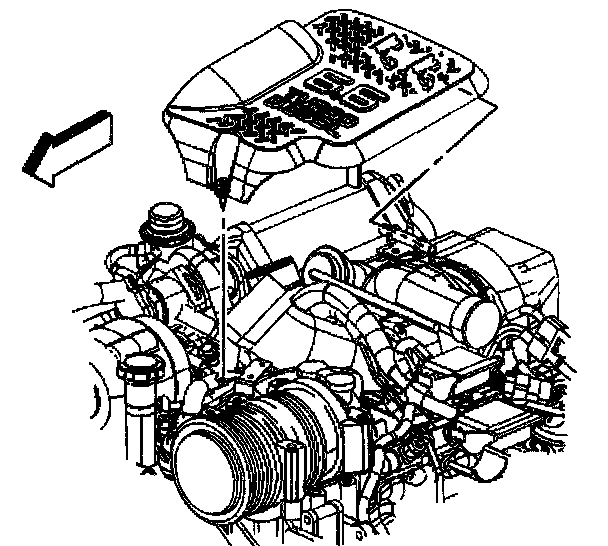
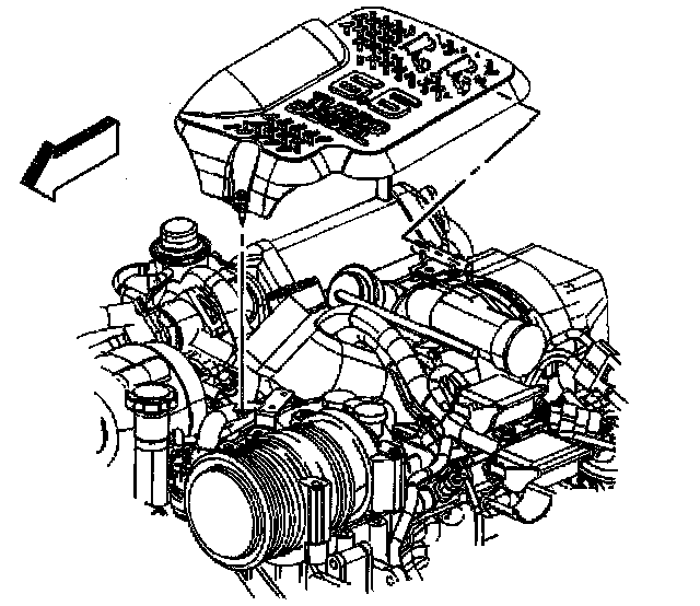
1. Remove the upper intake manifold sight shield using the following procedure:
1.1. Remove the retaining bolt in the front of the shield.
1.2. Lift-up on the front of the shield.
1.3. Lift the shield off the rear bracket.
2. Disconnect the battery negative cable.
3. Drain the engine coolant.
4. Remove the upper fan shroud.
5. Remove the drive belt.
6. Disconnect the A/C compressor clutch electrical connector.
7. Disconnect the A/C cut out switch electrical connector.
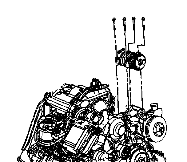
8. Remove the A/C compressor mounting bolts.
9. Move the A/C compressor with the hoses attached to the right side of the engine compartment.
10. Remove the nut retaining the generator positive cable to the generator.
11. Remove the positive cable from the generator.
12. Remove the clip holding the positive cable to the engine front cover.
13. Remove the bolt retaining the battery positive cable junction block to the power steering pump.
14. Move the generator positive cable and the junction block bracket aside.
15. Disconnect the generator electrical connector.
16. Disconnect the engine coolant temperature (ECT) sensor electrical connector.
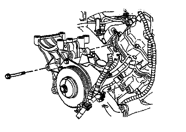
17. Remove the power steering pump mounting bracket and secure to the side.
^ Do not remove the power steering pump from the bracket.
^ The hoses and battery cables can remain on the power steering pump.
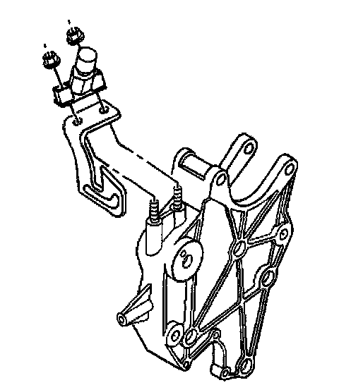
18. Remove the bolts retaining the fuel bleed valve and PCV oil separator bracket from the generator mounting bracket.
19. Remove the heater outlet hose bracket bolt from the generator bracket.
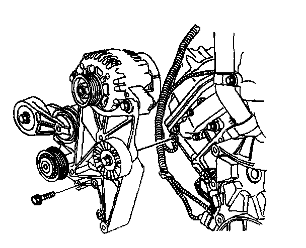
20. Remove the ribbed idler pulley.
21. Remove the generator mounting bracket and secure to the side.
^ The generator does not require removal.
^ The drive belt tensioner does not require removal.
22. Remove the oil fill tube.
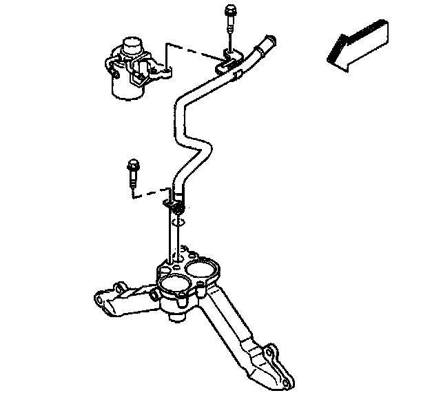
23. Remove the water outlet tube.
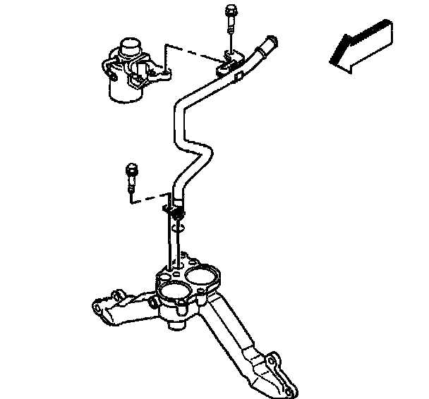
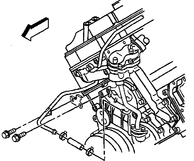
24. Remove the bolt retaining the heater pipe to the fuel filter assembly.
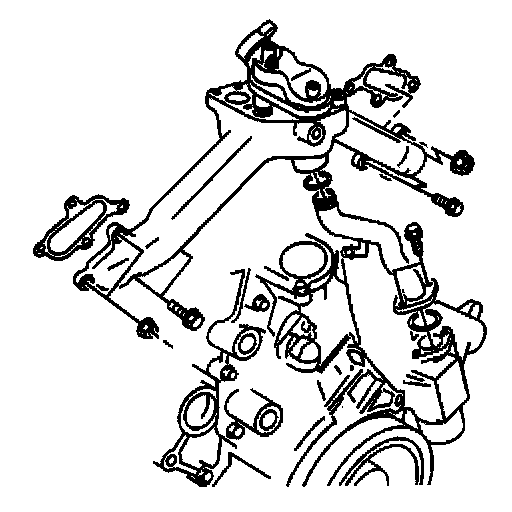
25. Remove the bolt retaining the heater pipe to the thermostat housing crossover.
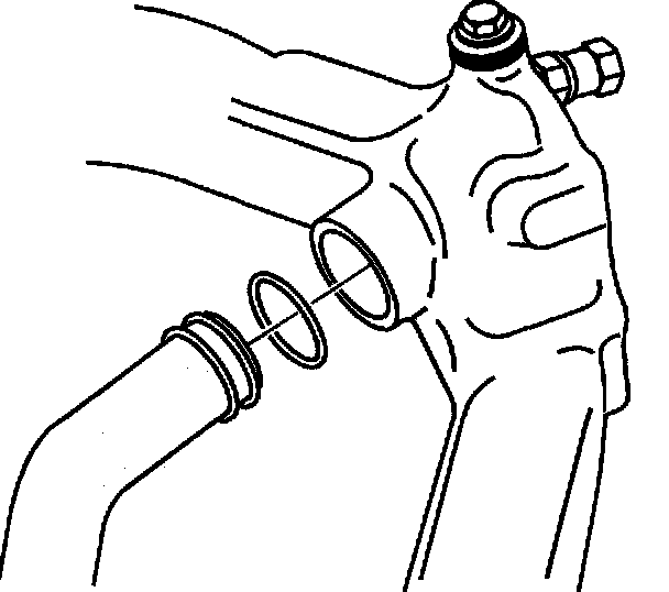
26. Remove the heater pipe with O-ring seal from the crossover.
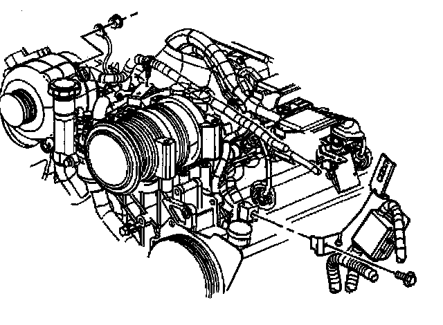
27. Remove the, hose and clamp 4 from the turbocharger outlet coolant pipe to thermostat bypass pipe.
28. Remove the fuel line bracket from the thermostat housing crossover.
29. Remove the cooling fan pulley.
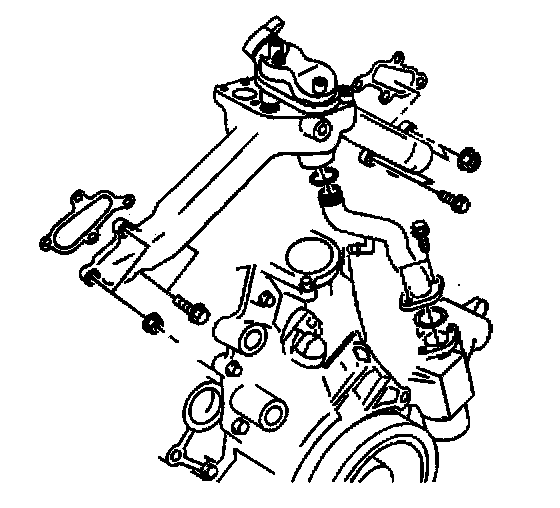
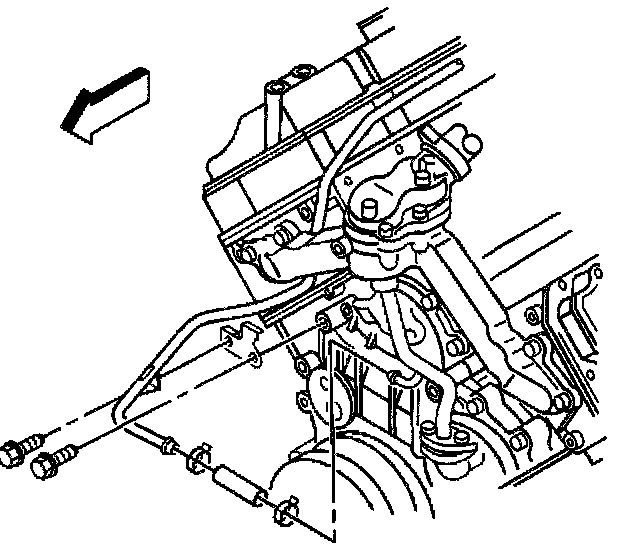
30. Remove the 2 thermostat housing crossover bolts and 2 nuts from the left cylinder head.
31. Remove the 2 thermostat housing crossover bolts and 2 nuts from the right cylinder head.
32. Remove the bypass pipe to water pump bolts.
33. Remove the thermostat housing crossover with the bypass pipe.
34. Remove the bypass pipe to water pump O-ring.
35. Remove the -bypass pipe from the thermostat housing crossover.
36. Remove the O-ring from the bypass pipe.
Inspection and Repair Procedure
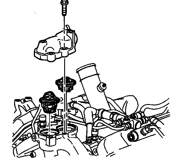
1. If required, remove the thermostat cover bolts.
2. Remove the thermostat cover.
3. Remove the thermostats with seals.
4. Remove the thermostat seals.
5. Remove the ECT sensor if replacing the thermostat housing crossover.
6. Clean the water crossover.
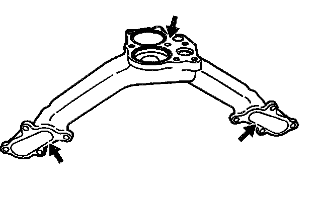
7. Clean the thermostat housing crossover mating surfaces.
8. Inspect the thermostat housing crossover for cracks.
9. Inspect the thermostat housing crossover mating surfaces for damage.
10. Replace the thermostat housing crossover if any damage is found.
11. Install the thermostats with the seals. The thermostat with the vent valves goes toward the rear of the engine. Install with the vent valves towards the rear of the engine.
12. Install the thermostat cover and gasket.
Notice: Refer to Fastener Notice in Service Precautions.
13. Install the thermostat cover bolts.
^ Tighten the thermostat cover bolts to 21 Nm (15 ft. lbs.).
14. If removed, install the ECT sensor.
^ Tighten the ECT sensor to 33 Nm (24 ft. lbs.).
Installation Procedure
1. Install a new O-ring to the bypass pipe. Lubricate the O-ring with coolant.
2. Install the bypass pipe to the thermostat housing crossover.
3. Install new thermostat crossover gaskets.
4. Install a new O-ring for the bypass pipe to the water pump.
5. Install the thermostat crossover with the bypass pipe.
Notice: Refer to Fastener Notice in Service Precautions.
6. Install the bypass pipe to water pump bolts.
^ Tighten the bypass pipe to water pump bolts to 21 Nm (15 ft. lbs.).
7. Install the thermostat crossover bolts and nuts.
^ Tighten the thermostat crossover bolts and nuts to 21 Nm (15 ft. lbs.).
8. Install the fuel line bracket and bolt.
^ Tighten the fuel line bracket bolt to 21 Nm (15 ft. lbs.).
9. Install the hose and clamp from the turbocharger outlet coolant pipe to thermostat bypass pipe.
10. Install a new O-ring sea] to the heater pipe.
11. Install the heater pipe to the thermostat housing crossover.
12. Install the bolt retaining the heater pipe to the thermostat housing crossover.
^ Tighten the heater pipe bolt to 21 Nm (15 ft. lbs.).
13. Install the bolt retaining the heater pipe to the fuel filter assembly.
^ Tighten the heater pipe bracket bolt to 21 Nm (15 ft. lbs.).
14. Install the generator mounting bracket and bolts.
^ Tighten the generator mounting bracket bolts to 50 Nm (37 ft. lbs.).
15. Install the ribbed idler pulley and the bolt.
^ Tighten the idler puller bolt to 43 Nm (32 ft. lbs.)..
16. Install the heater outlet hose bracket bolt.
^ Tighten the bracket bolt to 21 Nm (15 ft. lbs.).
17. Install the nuts retaining the fuel bleed valve and PCV oil separator bracket from the generator mounting bracket.
^ Tighten the bracket nuts to 25 Nm (18 ft. lbs.).
18. Install the power steering pump mounting bracket and bolts.
^ Tighten the power steering pump mounting bracket bolts to 46 Nm (34 ft. lbs.).
19. Install the water outlet tube.
20. Position the generator positive cable.
21. Install the generator positive cable in the clip on the engine front cover.
22. Install the generator positive cable and the retaining nut to the generator.
^ Tighten the generator positive cable nut to 9 Nm (80 inch lbs.).
23. Install the battery positive cable junction block bracket and bolt to the power steering pump.
^ Tighten the junction block bracket bolt to 9 Nm (80 inch lbs.).
24. Connect the generator electrical connector.
25. Position the A/C compressor.
26. Install the A/C compressor mounting bolts.
^ Tighten the A/C compressor mounting bolts to 50 Nm (37 ft. lbs.).
27. Connect the A/C cut out switch electrical connector.
28. Connect the A/C clutch electrical connector.
29. Install the drive belt.
30. Install the upper fan shroud.
31. Fill the engine coolant.
32. Connect the battery negative cable.
33. Install the upper intake manifold sight shield.
^ Tighten the upper intake manifold shield bolt to 9 Nm (80 inch lbs.)