P0133 or P0153 (W/ Denso HO2S)
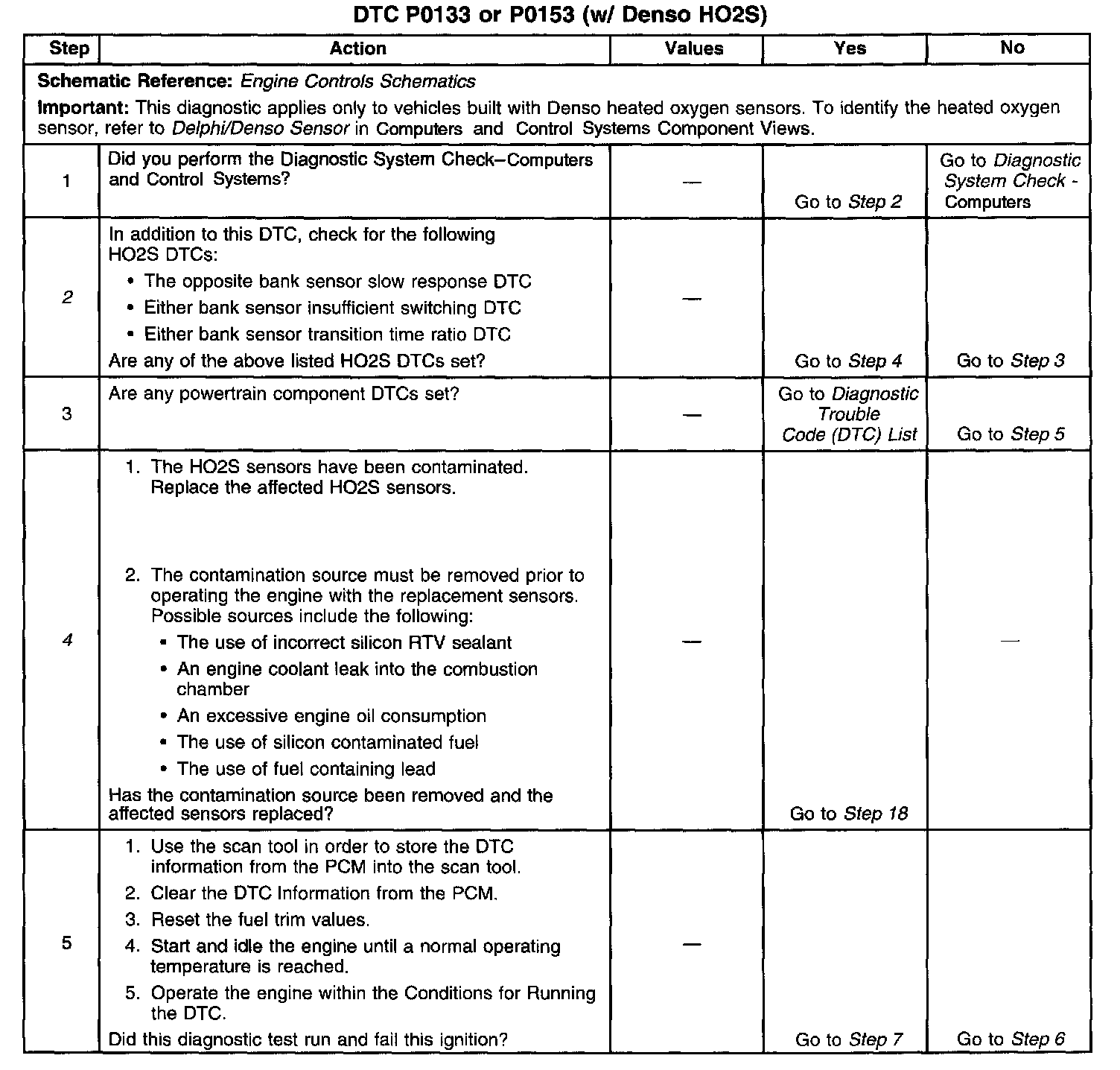
CIRCUIT DESCRIPTIONThis diagnostic applies only to vehicles built with Denso heated oxygen sensors. To identify the heated oxygen sensor refer to Delphi/Denso Sensor in Computers and Control Systems Component Views.
The Powertrain Control Module (PCM) continuously monitors the Heated Oxygen Sensor (HO2S) activity for 100 seconds. During the monitor period, the PCM counts the number of times that the HO2S responds from rich to lean and from lean to rich and adds the amount of time it took to complete all transitions. With this information, the PCM can determine the average time for all transitions. If the average response time is too slow, a Diagnostic Trouble Code (DTC) sets
The PCM determines the lean to rich transition when the HO2S voltage changes from less than 300 mV to more than 600 mV. The PCM determines the rich to lean transition when the HO2S voltage changes from more than 600 mV to less than 300 mV. An HO2S that responds too slowly is most likely defective. Replace the HO2S.
CONDITIONS FOR RUNNING THE DTC
^ DTCs P0101, P0102, P0103, P0106, P0107, P0108, P0112, P0113, P0117, P0118, P0121, P0122, P0123, P0200, P0300, P0401, P0404, P0405, P0410, P0440, P0442, P0446, P0452, P0453, P1120, P1125, P1220, P1221, P1258, P1404, P1415, P1416, P1514, P1515, P1516, P1517, or P1518 are not set.
^ The Engine Coolant Temperature (ECT) is more than 65°C (149°F).
^ The engine run time is more than 160 seconds.
^ The EVAP purge solenoid command is more than 0 percent.
^ The Mass Air Flow (MAF) is between 23-50 g/s.
^ The engine speed is between 1,200-3,000 RPM.
^ Vehicles without Throttle-actuated Control (TAC), the Throttle Position (TP) is more than 5 percent.
^ Vehicles with Throttle-actuated Control (TAC), the Throttle Position (TP) indicated angle is 5 percent more than the value observed at idle.
^ The loop status is closed.
^ The ignition 1 signal is between 9-18 volts.
^ The fuel tank level remaining is more than 10 percent.
^ Intrusive tests are not in progress.
^ The scan tool output controls are not active.
CONDITIONS FOR SETTING THE DTC
^ The rich-to-lean and lean-to-rich response time average is more than a calibrated value.
^ The above conditions are met for 100 seconds.
ACTION TAKEN WHEN THE DTC SETS
^ The control module illuminates the Malfunction Indicator Lamp (MIL) on the second consecutive ignition cycle that the diagnostic runs and fails.
^ The control module records the operating conditions at the time the diagnostic fails. The first time the diagnostic fails, the control module stores this information in the Failure Records. If the diagnostic reports a failure on the second consecutive ignition cycle, the control module records the operating conditions at the time of the failure. The control module writes the operating conditions to the Freeze Frame and updates the Failure Records.
CONDITIONS FOR CLEARING THE MIL/DTC
^ The control module turns OFF the Malfunction Indicator Lamp (MIL) after 3 consecutive ignition cycles that the diagnostic runs and does not fail.
^ A current DTC, Last Test Failed, clears when the diagnostic runs and passes.
^ A history DTC clears after 40 consecutive warm-up cycles, if no failures are reported by this or any other emission related diagnostic.
^ Use a scan tool in order to clear the MIL and the DTC.
DIAGNOSTIC AIDS
IMPORTANT: Never solder the HO2S wires. For proper wire and connector repairs, refer to Wiring Repairs or Connector Repairs in Diagrams. Check for the following conditions:
^ Inspect for an improperly installed air cleaner outlet duct.
^ Inspect the air cleaner outlet duct for a collapsed duct, restrictions, or a missing or plugged air filter.
^ Inspect the throttle body and the intake manifold for vacuum leaks.
^ Inspect for a damaged or blocked throttle body inlet.
^ Inspect the exhaust system for corrosion, leaks, or loose or missing hardware. Refer to Exhaust Leakage in Exhaust System.
^ Verify that the HO2S is installed securely and the pigtail harness is not contacting the exhaust manifold or wires.
^ Check for any HO2S contamination.
^ inspect the vacuum hoses for splits, kinks, and proper connections.
^ Test for excessive water, alcohol, or other contaminants in the fuel. Refer to Alcohol/Contaminants-in-Fuel Diagnosis. Fuel
^ Verify that the PCM sensor grounds are clean, tight, and properly positioned.
An intermittent may be caused by any of the following conditions:
^ A poor connection
^ Rubbed through wire insulation
^ A broken wire inside the insulation
Thoroughly check any circuitry that is suspected of causing the intermittent complaint. Refer to Testing for intermittent and Poor Connections in Diagrams.
If a repair is necessary, then refer to Wiring Repairs or Connector Repairs in Diagrams.
TEST DESCRIPTION
Steps 1-5:
Steps 6-9:
Steps 10-19:
The numbers below refer to the step numbers on the diagnostic table.
2. HO2S contamination is indicated if multiple response, switching or time ratio HO2S DTCs are set.
4. An HO2S contaminated by silicon will have a white, powdery deposit on the portion of the HO2S that is exposed to the exhaust stream. The usual cause of silica contamination is the use of unapproved silicon RTV engine gasket material or the use of silicon based sprays or fluids within the engine.
If the cause of this contamination is not corrected, the replacement HO2S will also be contaminated.
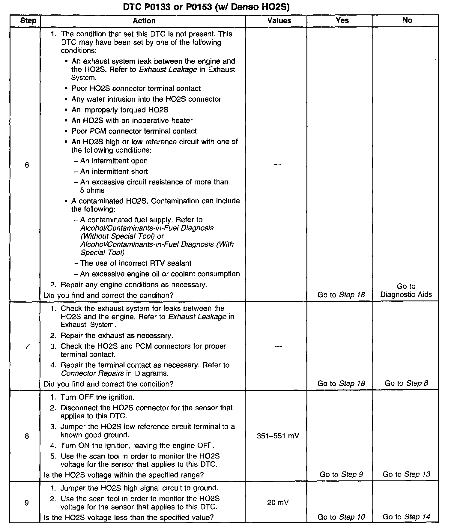
7. Even small exhaust leaks can cause slow response from the HO2S.
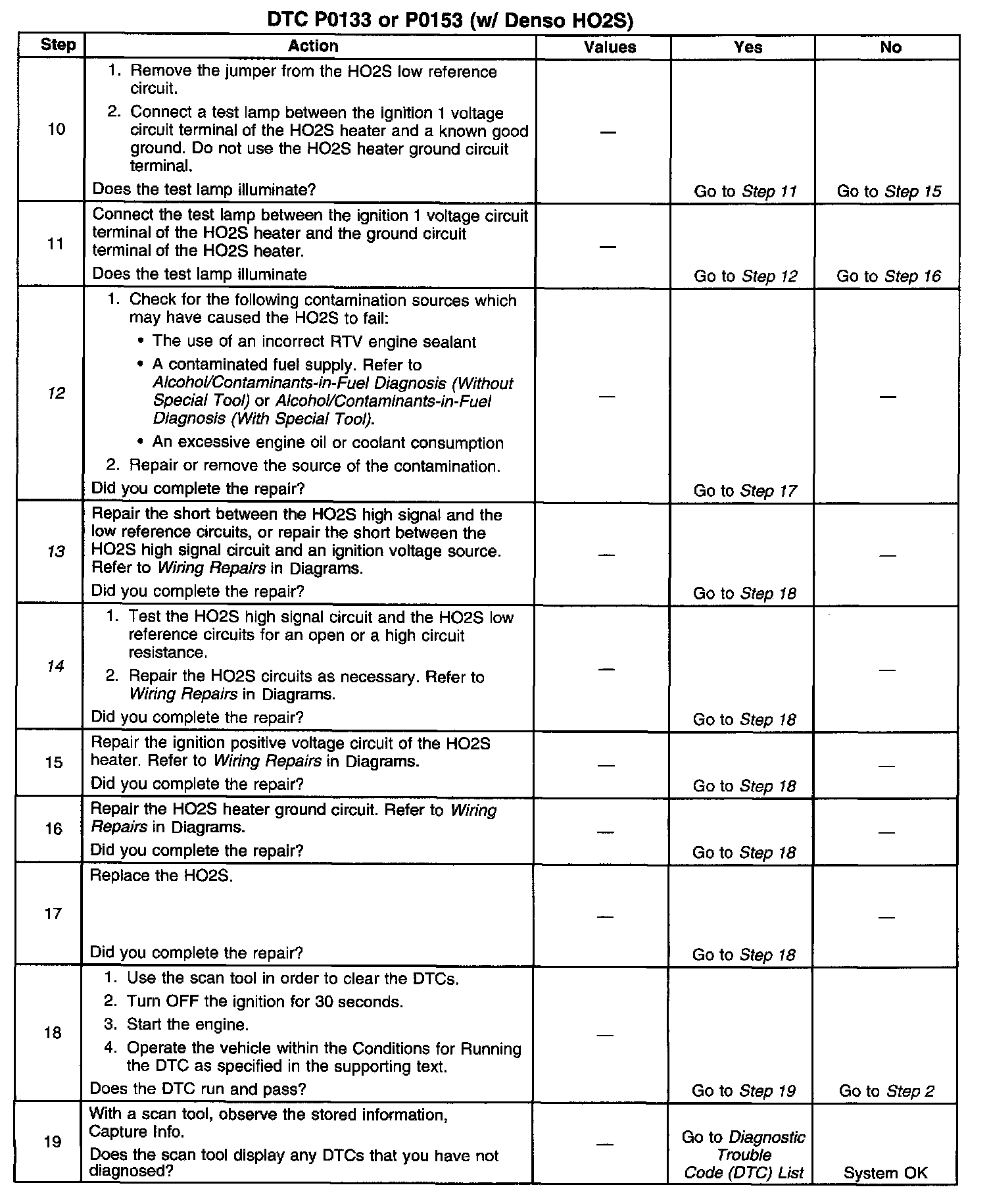
12. An HO2S contaminated by silicon will have a white, powdery deposit on the portion of the HO2S that is exposed to the exhaust stream. The usual cause of silica contamination is the use of unapproved silicon RTV engine gasket material or the use of silicon based sprays or fluids within the engine. If the cause of this contamination is not corrected, the replacement HO2S will also be contaminated.
13. If the voltage observed in step 8 is less than the range specified, a short between the high signal circuit and the low reference circuits, or a short between the high signal circuit and ground is indicated. With the HO2S and the PCM disconnected, the resistance between the high signal circuit and low reference circuits and the resistance between the high signal circuit and ground should measure infinite.
If the voltage observed in step 8 is more than the range specified, a short between the high circuit and an ignition voltage source is indicated.
14. If the voltage observed in step 9 is not less than the voltage specified, a high resistance high signal or low reference circuit is indicated.
Good circuit continuity measures less than 5 ohms with the PCM and the sensor disconnected. Measure between the PCM connector and the HO2S connector. Ensure the PCM terminal contact is good.